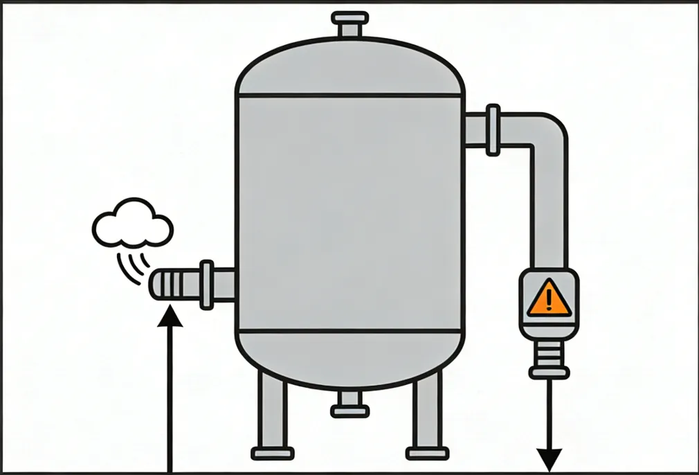
Desiccant air dryers are designed to remove water vapor and deliver stable dew point performance for industrial compressed air systems. During operation, you may notice air exhausting from the regeneration (purge) outlet.
But not all exhaust is a fault.
In practice, dryer exhaust falls into two categories:
Normal regeneration exhaust (expected purge/venting): intermittent and tied to tower switching and regeneration steps.
Abnormal continuous exhaust (fault condition): exhaust that continues around the clock, shows little change in sound/flow, or causes pressure to drop sharply.
Abnormal exhaust wastes energy, reduces available system pressure, and can disrupt production. This guide provides a practical troubleshooting sequence that follows two efficient rules:
Troubleshooting principles
External before internal: verify system conditions and leaks before opening the dryer.
Electrical/controls before mechanical: confirm the “command” is correct before replacing valves or seals.
Safety note: Compressed air systems can be dangerous. Before inspection or disassembly, isolate the dryer, depressurize safely, and follow lockout/tagout procedures. If you are not qualified, involve trained maintenance personnel.

Step 1 — Identify the Exhaust Type (Avoid Misdiagnosis)
What “normal” regeneration exhaust looks like
Normal exhaust varies by dryer type:
Heatless / low-heat dryers: exhaust occurs mainly during regeneration and is typically intermittent.
Heated regeneration dryers: exhaust is usually lower in volume and may be more concentrated toward the later part of regeneration, depending on design.
Key observation points
Use these quick checks:
A) Pattern
Normal: intermittent; aligned with tower switching; may start strong then taper.
Abnormal: continuous and steady, or long-term heavy blow with no clear cycling behavior.
B) Correlation with tower switching
Check tower pressure gauges (or the HMI/indicator).
Normal: exhaust behavior changes when the tower switches.
Abnormal: exhaust continues unchanged regardless of tower status.
C) Duration
Compare with the manual’s cycle specification (many systems are in the ~1–2 hours per cycle range, but your unit’s design is the authority).
Normal: exhaust duration matches cycle logic.
Abnormal: exhaust never stops, day and night.
Rule out operator-mode causes first
Continuous exhaust can be caused by mode/settings rather than hardware failure:
“Regeneration delay” / extended regeneration
Manual exhaust / manual purge
Maintenance test mode
Return the dryer to AUTO, then observe 1–2 complete switching cycles. If exhaust still does not stop, continue to Step 2.
Step 2 — Check Electrical & Control Signals (Fix “Wrong Command” First)
The control system is the “brain” that decides when to switch towers and when to vent. A wrong signal can keep an exhaust valve energized and venting continuously.
2.1 Check alarms, PLC status, and sensors
Look for HMI/PLC alarms such as:
Pressure sensor fault
Solenoid fault
“Pressure signal lost” / invalid pressure reading
If a pressure signal is missing or unstable:
Inspect the pressure sensor wiring/terminals for looseness.
Check for a blocked sensing port (oil/dust contamination is common).
Measure the sensor output if applicable (many industrial transmitters use 4–20 mA).
Replace the sensor if the signal is abnormal and wiring is confirmed good.
2.2 Verify tower switching function
Manually trigger a tower switch (if your control system allows it) and observe:
Does the dryer switch towers correctly?
Does exhaust behavior change or stop after switching?
If switching fails or logic is abnormal without clear mechanical binding:
The issue may be PLC program/parameter corruption or misconfiguration.
Restore correct parameters or involve the manufacturer/service team to reload the standard program.
2.3 Inspect solenoid valves (common cause of continuous exhaust)
Solenoids typically drive pilot air or direct exhaust valves.
Quick checks
Feel the coil temperature: continuous heating often indicates continuous energization (command or stuck output).
Confirm coil magnetism and correct power supply (commonly 24V DC or 220V AC, depending on design).
If the solenoid is energized continuously
Identify why the PLC output is staying ON (logic, sensor input, alarm interlock, manual mode).
Check the output module/relay if the PLC command is OFF but the solenoid remains powered.
If the solenoid valve is mechanically stuck
Remove and clean the valve core/spool; blow out debris with clean compressed air.
Replace aged seals if leakage persists.
Replace the solenoid valve if the coil is burned or the valve repeatedly sticks.
Step 3 — Inspect Switching Valves and Seals (Eliminate Mechanical Sticking/Leakage)
Switching valves (pneumatic ball valves/butterfly valves, etc.) control airflow direction. If a valve sticks or leaks internally, air can continuously vent through the regeneration path.
3.1 Confirm valve actuation and internal leakage
During a commanded tower switch, listen/observe for a clear valve action (“click”/movement).
Use soap solution at valve stem/body joints to identify external leaks.
If bubbles appear or internal leakage is suspected
Disassemble as required and inspect:
worn valve core/seat
debris on sealing surfaces
actuator travel/limit settings
Clean and lubricate where appropriate.
Replace damaged sealing surfaces or the entire valve if sealing cannot be restored reliably.
3.2 Check the regeneration exhaust valve and drain valve sealing
If the bottom regeneration exhaust valve or drain valve does not seal, you may see continuous low-to-moderate exhaust.
Practical isolation test
Close the upstream/downstream isolation valves around the exhaust path (if installed).
Monitor whether line pressure stabilizes.
If pressure still drops
Disassemble the exhaust valve:
warped valve disc/poppet
aged O-rings or gasket
contamination preventing full closure
Replace damaged parts and re-torque connections.
3.3 Check end-cover seals on the towers
If tower end-cover gaskets are damaged, air can leak in unintended ways and may appear as continuous exhaust.
Open and replace gaskets as needed.
Ensure mating surfaces are clean and bolts are tightened evenly.
Step 4 — Verify Pressure and Piping (Solve “Pressure-Abnormal” Triggers)
Pressure imbalance can cause the dryer to vent as part of protection logic or due to uncontrolled leakage.
4.1 Confirm inlet pressure is within the dryer’s operating range
If inlet pressure is too low, some dryers will enter protective venting or fail to complete switching.
Your example threshold: below 0.4 MPa (~4 bar) may be below the minimum working pressure for some systems (always confirm the manual).
Check
Compressor discharge pressure stability
Inlet piping restrictions
Prefilter differential pressure and element condition
A common rule-of-thumb from your text: if filter differential pressure exceeds 0.07 MPa (~0.7 bar), the element may need replacement (verify with the filter manufacturer).
4.2 Check tower pressure balance and check valves
If the pressure difference between towers is excessive (example: >0.1 MPa ≈ 1 bar), a stuck check valve can cause backflow and unintended venting.
Remove and clean the check valve core.
Replace if wear or sticking persists.
4.3 Find external leaks in piping and regeneration lines
Use soap solution on:
inlet/outlet flanges
regeneration piping
exhaust piping welds and joints
Repair by tightening bolts, replacing gaskets, or re-welding where appropriate.
4.4 Don’t ignore downstream system demand/leaks
If the receiver tank pressure is low due to downstream leaks or abnormal demand, the dryer may appear to be “always venting” while the system is constantly struggling to build pressure.
Coordinate troubleshooting with the downstream users and distribution network.
Step 5 — Special Operating Conditions (Avoid Missing the Real Trigger)
For heated regeneration dryers: check blower and heater
Blower failure → insufficient regeneration airflow → regeneration failure alarms and repeated exhaust attempts.
Check motor current, airflow, and impeller dust buildup.
Heater failure → regeneration temperature cannot reach setpoint
Measure heater resistance; replace if open circuit or failed.
For heatless dryers: check purge throttling/orifice and safety venting
A blocked throttling valve/orifice can raise regeneration pressure and trigger safety venting.
Remove and clean blockage, restore correct purge flow.
Check the condensate drain system
A blocked automatic drain can lead to excessive liquid accumulation, indirectly disturbing pressure behavior and control stability.
Clean the drain strainer and verify free drainage.
Step 6 — Preventive Maintenance to Stop Continuous Exhaust from Returning
Most “continuous exhaust” faults repeat because of contamination and neglected wear parts. Focus on these three habits:
Monthly cleaning/inspection of electrical components
Prevent dust/oil contamination from affecting solenoids and sensor signals.Seal inspection every 6–12 months (or per duty cycle)
Check switching valves and exhaust valve sealing; replace aged O-rings before leakage becomes continuous venting.Control inlet air quality
Keep oil/water carryover under control; replace prefilter elements on differential-pressure trend, not only by calendar.
Also keep a simple operating log:
exhaust frequency and duration
inlet pressure stability
tower pressure balance
any gradual increase in exhaust time (an early warning sign)
Core Takeaway
When a desiccant dryer vents continuously, the most efficient approach is:
Find the command source first (controls/sensors/PLC output), then inspect the actuator/valve.
Check external leaks and system pressure conditions before opening internal components.
If all external checks pass and exhaust remains continuous, the dryer may have internal damage or deformation (for example, tower internals or baffles). In that case, involve the manufacturer or a qualified service team and avoid dismantling core components without guidance.